프로세싱(Processing) 개발 툴을 분석하고 나면, 아두이노 개발 툴 소스 분석은 더 쉽다.
아두이노 개발 툴은 프로세싱 개발 툴 소스 depedency가 있거나 복사된 소스들이 많다. (정확히 역사는 어떻게 되었는지는 모르지만..^^;)
1. 소스를 다운받는다.
http://www.arduino.cc/en/Main/software 페이지에서 소스를 다운받는다.

2. 이클립스 프로젝트 환경 구축
이클립스 프로젝트를 하나 생성하고 다운받은 소스를 복사한다. 아두이노 개발 툴 안에 이클립스 설정이 파일이 있다.

아두이노 개발 툴의 build path를 살펴보면, processing-core를 참조하고 있다. (processing.core 패키지를 참조하고 있다.)

프로세싱 소스는 아래 위치에서 git로 다운받는다.
http://code.google.com/p/processing/source/checkout
프로세싱 코드는 2.0으로 다운받으면, processing.app.RunnerListener 인터페이스를 모두 상속해서 구현하지 않았다고 아두이노 개발 툴 소스의 Editor 클래스 컴파일 에러가 난다. API 구현해주면 깨끗하게 컴파일 완료된다.
|
public class Editor extends JFrame implements RunnerListener { …..
|
컴파일 완료된 상태
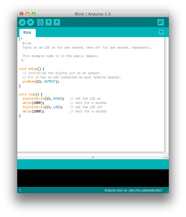
<아두이노 소스>

빌드 연동

프로세싱 소스 (core/src 디렉토리의 소스만 잘 빌드되면 됨)

3. 소스 디렉토리 확인
UI 부분은 프로세싱과 거의 동일하다.

디버그 관련 패키지가 들어가 있다. 컴파일도 하고 실행했을 때 output 처리하는 것들. arduino 보드에 올리는 클래스들이 담겨 있다.

프로세싱 개발 툴은 java 기반이지만, 아두이노 개발 툴은 자바 기반 언어대신 C 언어의 특성을 가지고 있다. (그래서 antlr는 사용할 필요가 없다.)
그러나 화면에 출력되는 문법에 맞는 색상을 칠해주는 패키지이다.

이 외. 운영체제(플랫폼)에 맞는 다양한 작업 패키지들이 있다. 여기도 프로세싱 개발 툴처럼 jna가 쓰이고 있다.
processing.app.linux, processing.app.windows, processing.app.macosx
4. 빌드
빌드는 build 디렉토리에 있는 build.xml를 가지고 ant 컴파일 하면 된다.
build:
revision-check:
windows-checkos:
subprojects-build:
compile:
....
[launch4j] Compiling resources
[launch4j] Linking
[launch4j] Successfully created G:\workspace\arduino-1.0\build\windows\work\arduino.exe
BUILD SUCCESSFUL
Total time: 44 seconds
'아두이노' 카테고리의 다른 글
| 아두이 개발 툴 없이 아두이노(Arduino) 소스 컴파일 해보기 (1) | 2011.12.30 |
|---|---|
| 아두이노 (arduino) 개발 툴 1.0 소스 분석 (0) | 2011.12.29 |
| 프로세싱 언어와 PDE 코드 살펴보기 #2 (1) | 2011.12.20 |
| 프로세싱 언어와 PDE 코드 살펴보기 #1 (2) | 2011.12.20 |
| 아두이노(arduino)와 선풍기 연결 (1) | 2011.12.20 |


 ir-example.fz


 009_ATmega128_리모콘[1].pdf


